
Prestudy case study · UXO survey consultancy
See more of the magnetic signature with TrueMag.
TrueMag’s three-axis fluxgate approach preserves the magnetic signature in three dimensions. Capture directional changes that can be weak in total-field data, bring more observations into target interpretation, and build a richer basis for survey quality assurance.
Technical use case for marine UXO consultants, supported by an illustrative model and independent fluxgate survey research.
Scenario
Bring more information to every target pick.
Reliable target assessment starts with the information collected at the sensor. A weak total-field anomaly can reflect the direction of a target’s magnetic disturbance as well as its strength. TrueMag’s vector approach preserves both, giving interpreters more of the measured signature to work with.
Caesium-vapour instruments such as the G-882 measure scalar total field. Modern MagElement instruments also remain scalar. A calibrated three-axis fluxgate measures Bx, By and Bz, from which total field F = √(Bx² + By² + Bz²) can be calculated. The same acquisition therefore supports component analysis and a derived total-field product.[1][2]
The three strongest data advantages
Three reasons to choose vector magnetometry.
Capture anomalies beyond their scalar expression
For disturbances small relative to Earth's field, scalar total field mainly responds to the anomaly component parallel to the background. A three-axis sensor also records the perpendicular components, preserving information that can be strongly suppressed in total-field data.[3]
Consultant value: retain directional evidence for targets whose scalar expression is weak.
Build a better-constrained target model
Component amplitudes, signs and spatial shapes provide additional observations for joint inversion of target position and magnetic moment. Used with calibrated attitude and navigation data, these observations can help distinguish between competing source models.[3]
Consultant value: use the full component signature to support position and magnetic-moment estimates, with uncertainty assessed across the model.
Gain more control over survey data quality
Vector measurements provide inputs for sensor and platform calibration, while time-aligned motion data support component-level residual and motion-correlation analysis. In synchronised arrays with surveyed baselines, they also add spatial differences in each component alongside total-field differences.
Consultant value: a richer basis for separating target signatures from acquisition effects and documenting the quality of the interpreted data.
Modelled example
A direction change can hide in total field.
Take a uniform 50,000 nT background and a local disturbance of 10 nT. When parallel to the background, it changes total field by 10 nT. When perpendicular, its exact total-field effect is only about 0.001 nT. The vector disturbance remains 10 nT in both cases.
The model uses ΔF = |B₀ + b| − |B₀|. For small anomalies, ΔF ≈ B̂₀ · b; a purely transverse disturbance enters total field at second order, approximately |b|²/(2|B₀|). This concerns the anomaly direction relative to Earth's field, independently of the caesium sensor's optical axis.[3]
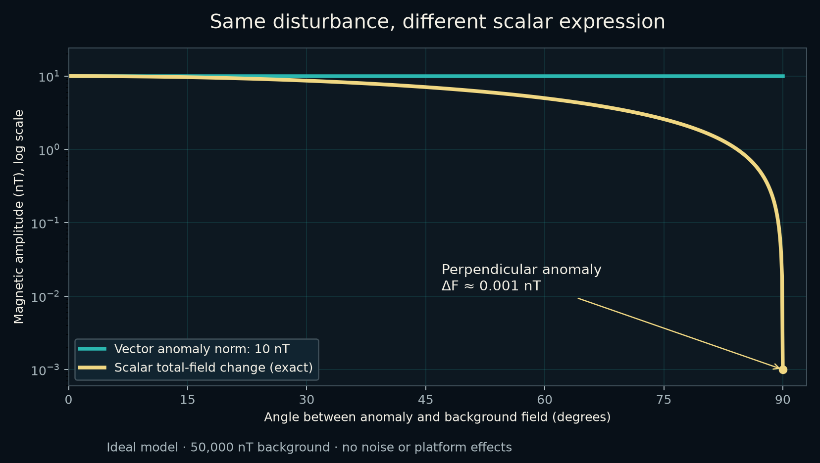
By retaining the transverse response, vector acquisition gives the interpreter access to information strongly suppressed in this scalar example. A real target’s field varies along the survey line; the practical benefit depends on that geometry and on the quality of the calibrated components.
The calculated width is an initial anomaly footprint. Operational line spacing also accounts for target orientation, burial, position uncertainty and the data quality needed for detection and interpretation. No synthetic-aperture gain is included in these estimates.
Processing development opportunity
Build a richer target signature along the survey track.
A moving TrueMag records successive three-axis observations of a target from known positions. A proposed synthetic-aperture approach would combine those observations through a spatial target model, using the changing component amplitudes and signs to reinforce a consistent target response across the pass.
The three-axis contribution is the directional information available to that fit. Calibrated vectors can provide observations that are weak in a scalar projection, creating an opportunity to strengthen off-track detection and constrain target location and magnetic moment. Published fluxgate work already demonstrates profile-based dipole inversion; a TrueMag synthetic-aperture implementation would be a separate development.[7]
For UXO consultants, the potential benefit is more useful target evidence from the same acquisition pass, with a path towards fewer repeat passes or wider accepted line spacing. The gain would need to be established against scalar and vector processing using the same survey geometry and acceptance criteria.
Here, synthetic aperture means combining spatial samples of a quasi-static magnetic signature through a model, rather than radar-style phase focusing. Scalar data can also benefit from profile processing. Three channels do not imply a fixed sensitivity or swath multiplier, and correlated noise, attitude errors and model mismatch can limit any gain. The existing swath model already includes a heuristic integration allowance; additional gain cannot simply be added to it.
TrueMag measurement architecture
Connect magnetic detail with motion context.
TrueMag pairs three-axis magnetic sensing with tightly coupled motion sensing and network timing. This architecture preserves the information needed to investigate motion-related artefacts, align measurements with navigation and develop a traceable processing workflow.
Calibrated components support a derived total-field product; attitude-referenced processing opens access to directional anomaly analysis. Multiple units extend that information across a survey array, with component differences along each measured baseline.
Component quality depends on offset, gain, orthogonality, temperature, platform calibration and time alignment.[5] At 50,000 nT, a 0.01° attitude error can mix about 8.7 nT into a transverse component in the worst geometry. A single unit does not measure a spatial gradient; one baseline does not independently recover a full gradient tensor.
Value for UXO consultants
Make every survey pass more informative.
TrueMag’s vector approach gives your interpretation team more ways to interrogate the same survey record. Analyse total field for continuity with established workflows, then use the calibrated components to examine anomaly direction, test source models and investigate residual acquisition effects.
That richer record can support a more defensible target assessment: an interpretation can be checked against component amplitudes, signs and spatial structure, alongside the scalar anomaly. In an array, component differences add further observations across the swath.
For consultants shaping future survey specifications, TrueMag offers a route to specifying the information needed for better interpretation and QA. We welcome consultant-led evaluations that demonstrate the contribution of vector data under the target, altitude and coverage requirements of your project.
Explore TrueMag for your next survey
Build your next survey around richer magnetic data.
Bring directional anomaly information, component-level interpretation and motion-aware data analysis into your UXO workflow. TrueMag is being developed to make those capabilities available in a compact subsea instrument, supporting consultant-led assessment from acquisition through interpretation.
Three-axis fluxgate sensing also avoids caesium optical dead-zone constraints, adding installation flexibility alongside its data advantages.
Explore TrueMag for UXO surveys Read the AUV UXO prestudyTechnical basis
References
- Geometrics: G-882 Marine Magnetometer. Manufacturer measurement principle, operating envelope and published noise specifications.
- Geometrics: MagElement Marine Magnetometer. Confirms that the newer instrument remains a total-field scalar magnetometer.
- Wigh et al.: Inference of unexploded ordnance (UXO) by probabilistic inversion of magnetic data. Dipole modelling, scalar projection and uncertainty in UXO source inference. The illustrated angular comparison is our calculation, not a result from this paper.
- Oehler et al. (2024): Processing of unmanned underwater vehicle vector magnetometer data. Sensor calibration and correction of AUV magnetic effects; independent research on other instruments.
- Bartington Instruments: Fluxgate measurement FAQ. Axis orthogonality and correction matrices.
- Brighouse et al. (2024): Inverse modelling and classification of magnetic responses to improve marine unexploded ordnance rationalization. Section 2.1 documents G-882 acquisition, survey geometry and observed detection of 25 kg items; the paper analyses 3,027 target responses across 18 offshore projects.
- Munschy et al. (2007): Magnetic mapping for the detection and characterization of UXO: Use of multi-sensor fluxgate 3-axis magnetometers and methods of interpretation. Demonstrates profile-based dipole inversion with fluxgate acquisition; cited as related processing work, not as validation of a TrueMag synthetic-aperture gain.
Prepared 29 October 2026. TrueMag is a prototype. Independent field results and ideal calculations are identified separately; improved detection, localisation or coverage requires project-specific validation. Passive magnetic data alone do not identify UXO or establish clearance.